Infineon’s Multi-Core Debug Solution (MCDS) provides non-intrusive, parallel trace output that is a very powerful tool to analyze and debug AURIX(TM)-based real-time systems in full operation. Learn how to maximize its benefit for comprehensive timing analysis.
Advantages at a Glance
On-Chip Tracing
On-chip tracing via MCDS is supported by AURIX emulation devices and production devices with miniMCDS. The extra costs and form factor requirements for tracing are very low compared to external, third party hardware-based tracing solutions.
Learn more
Non-Intrusive Tracing
MCDS-based trace recording is decoupled from the applications running on AURIX; there is no mutual impact on runtime performance of code execution and trace recording. Therefore, the trace files generated via MCDS are perfectly suited for detailed in-depth analysis of the runtime behavior, load issues and potential performance bottlenecks.
Multi-Core Tracing
Infineon’s MCDS supports simultaneous trace output for up to two processor cores.
Negligible Tracing Overhead for Timing Analysis
The tracing overhead required to capture timing information is typically quite small compared to the overall trace overhead that is mainly determined by the amount of application internal data and communication data to be traced in order to fully understand all issues that may occur during runtime. In many cases, all the timing information required is already present in the trace logs.
Comprehensive Timing Analysis Using the INCHRON chronSUITE
The chronSUITE imports traces generated by the MCDS Trace Viewer. The chronSUITE extracts the label information from the respective ELF files and interprets the trace information based on a highly configurable, generic mechanism. The chronSUITE complements Infineon’s MCDS Trace Viewer by generating comprehensive statistical reports and by providing state-of-the art graphical representations and automated analysis capabilities.
Continuous Tracing Without Trace Size Limitations
In case the trace recording is controlled by the chronSUITE, MCDS trace logs can be recorded continuously with no file size limitations other than the available mass storage space on the trace PC. The INCHRON chronSUITE efficiently handles trace files of sizes in the GB range. Hence the real-time behavior can be analyzed conveniently, and the root causes of any issues found can be analyzed in depth.
Designed for the Development of Safety Critical Systems
Many safety requirements directly translate into runtime performance requirements, in particular timing requirements. Thus, in order to meet all relevant timing requirements – under all circumstances and all the time – is an important prerequisite for systems that are considered to be safe. Analyzing violations of timing requirements is often tantamount to digging deeply into the root causes of safety issues. Timing requirement violations caused by applications that compete for shared resources are often perceived as sporadic in nature, as such resource conflicts are due to rare coincidences and therefore very difficult to reproduce. It is among the core competencies of the chronSUITE to detect and analyse any such issues reliably. Along with the safety features provided by Infineon’s AURIX platform, developers are well prepared to deal with many sorts of safety challenges.
Seamless Integration With Tools for Advanced Real-Time System Development
Advanced real-time system development as promoted by INCHRON does not only comprise effective means to analyse recorded traces; it also focuses on avoidance and anticipation of timing issues even before those might occur on target hardware. For this purpose, the INCHRON chronSUITE offers tools for model-based simulation of the real-time behaviour of systems, for the calculation of best and worst case response times, and for the automated optimization of real-time systems. Moreover, the chronSUITE provides all means required for virtual verification with respect to timing requirements. All these tools are seamlessly integrated into the chronSUITE‘s graphical user interface and work hand-in-hand, thus enabling developers to design real-time systems first time right and of excellent quality.
Learn more
Capturing MCDS Traces
Configuration and Control Using the INCHRON chronSUITE
MCDS tracing can be configured and started via the chronSUITE. The chronSUITE supports trace recording and visualization in just one step, as well as continuous recording of trace files of arbitrary sizes. All configuration information is stored inside a JSON (JavaScript Object Notation) file. There is no need to adapt the trace configuration to a new version of the applications running on AURIX.
Configuration and Control Using Infineon’s MTV
Alternatively, MCDS tracing can be configured and started via Infineon’s MCDS Trace Viewer (MTV). In this case, the MTV configuration file must be adapted to match the addresses specific to the respective version of the application running on AURIX.
Importing MCDS Traces Into the INCHRON chronSUITE
[Click to enlarge]
MCDS Traces
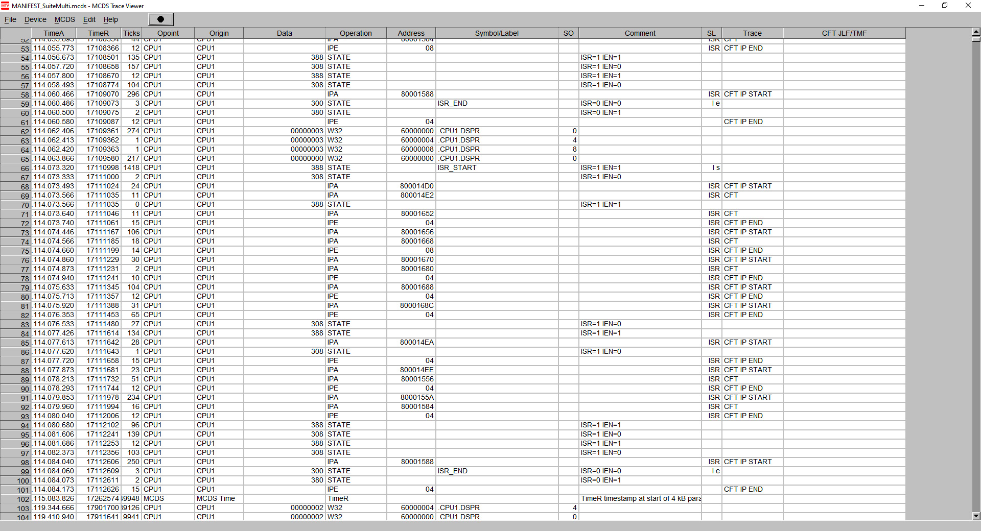
The screenshot above shows an MCDS trace as displayed by Infineon’s MCDS Trace Viewer. The information captured in MCDS traces is rather low-level. It basically comprises time stamps, CPU information, data values, operation types and symbols. All of this information is very helpful for experienced users. However, a comprehensive timing analysis requires more information at a reasonable level to compare measurement results with the timing requirements a system has to meet in order to work correctly and reliably. The task state information for instance is essential for timing analysis.
So, in order to perform timing analysis, the MCDS trace output does not only have to be converted into a format that can be processed by the INCHRON chronSUITE; an adequate amount of higher-level information has to be added as well to identify things like interrupt service routines, tasks, and task states.
Adding Information: A Generic Approach
In order to add such information, INCHRON applies a generic approach that does not depend on the operating system in use. The required information is specified in a JSON file; it is just another section in the exact same JSON file that contains the trace configuration if MCDS tracing is configured and started via the chronSUITE.
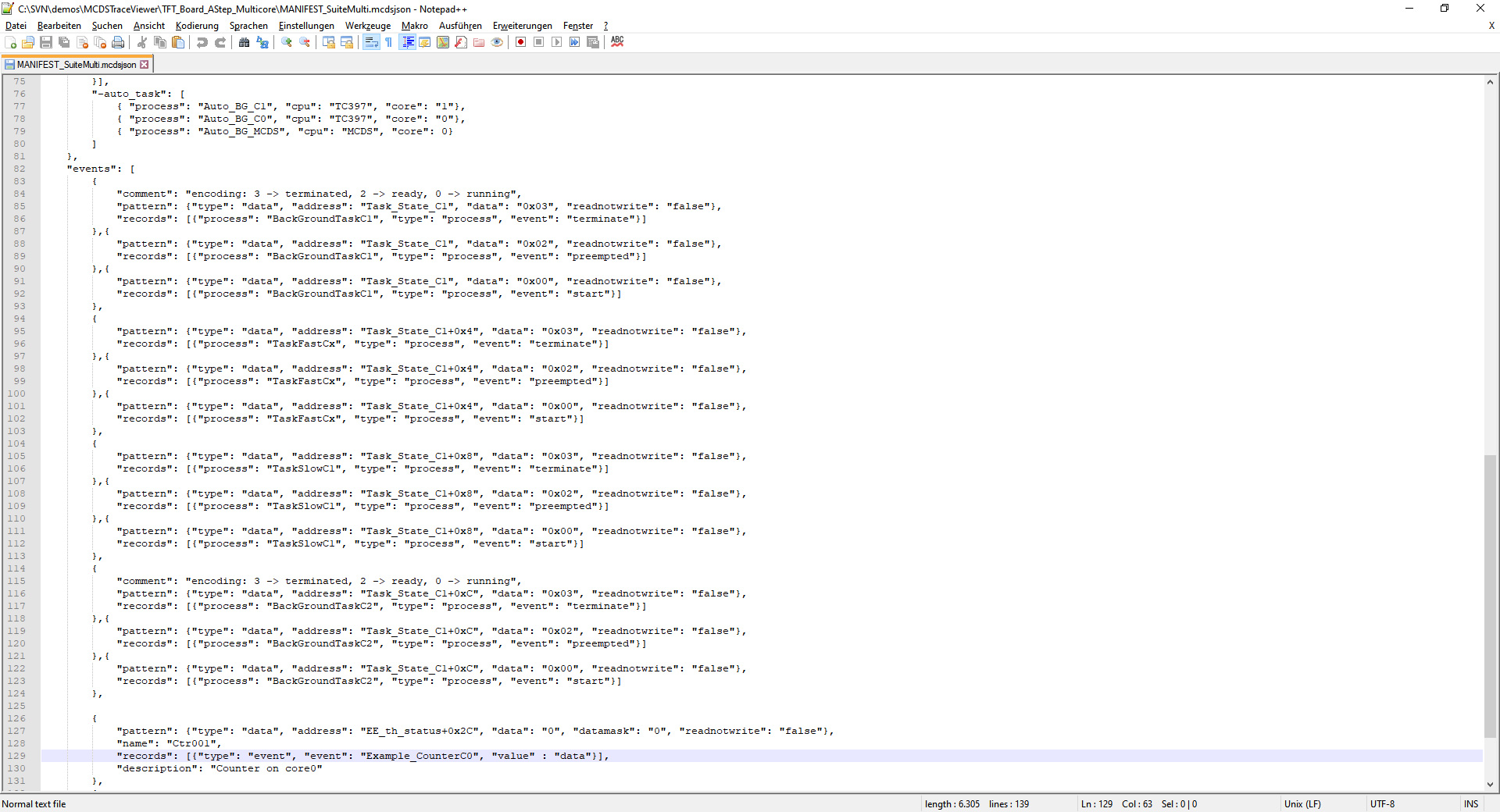
The screenshot below shows an excerpt from an example JSON trace confguration file; the excerpt covers the definition of the task states as well as a variable that serves as a counter. Both the task states and the value of the counter can be plotted into the same chart. The creation of a suitable JSON configuration file is basically a one-time effort specific to the application running on AURIX. Only a small extra effort will be necessary to maintain the JSON file during the lifecycle of a development project.
[Click to enlarge]
Labels are Read From ELF Files
The MCDS Trace Importer of the INCHRON chronSUITE resolves variable addresses and function addresses. Therefore, no manual configuration is required to display all labels of variables and functions captured in the trace file.
Visualizing MCDS Traces
[Click to enlarge]
Optimized Trace Visualization
The graphical user interface of the chronSUITE is designed to fully meet the demands of professional users in terms of performance, flexibility, efficiency and reliability.
Multi-Core Support
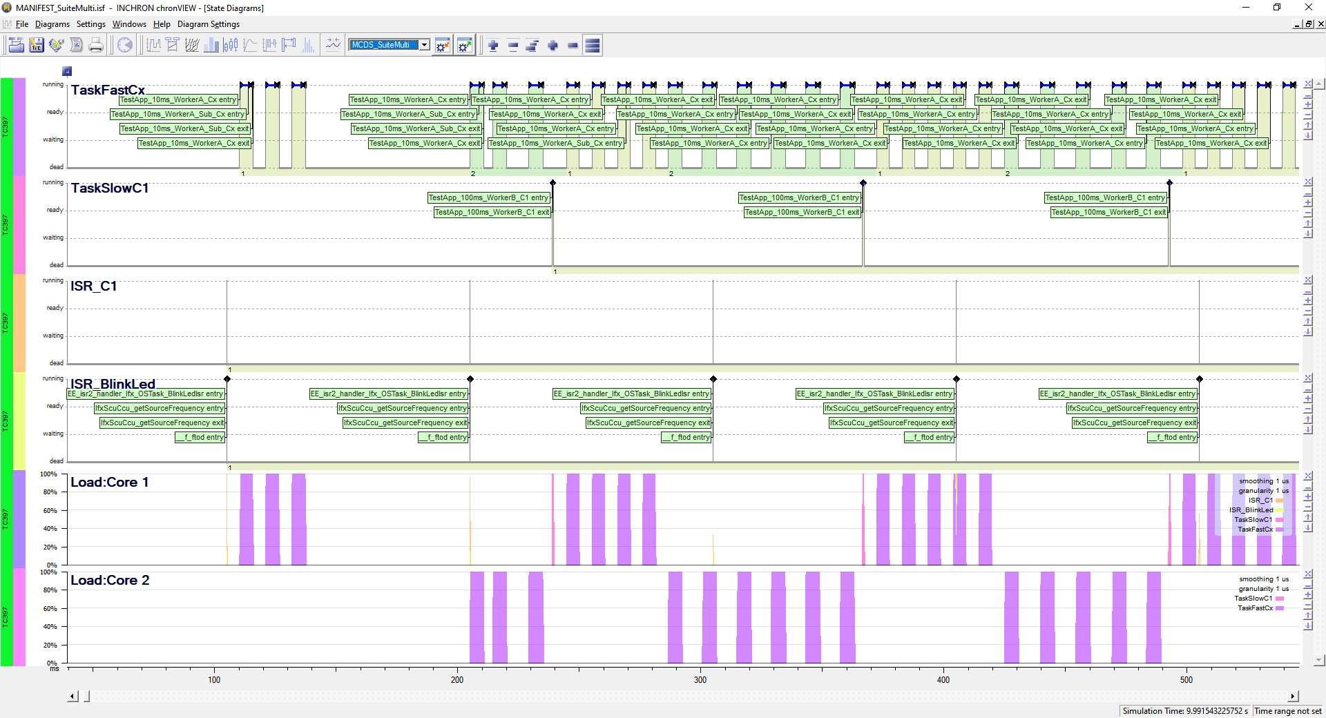
Infineon’s MCDS supports simultaneous trace recording of up to two cores. In the example shown above, the top line in the process state chart shows the behavior of the task TaskFastCx, that is running alternately on core 1 and core 2, while TaskSlowC1 and the interrupt service routine are tied to core 1. The processor load for each processor is shown in the lower third of the screenshot above.
[Click to enlarge]
Digging Into the Details
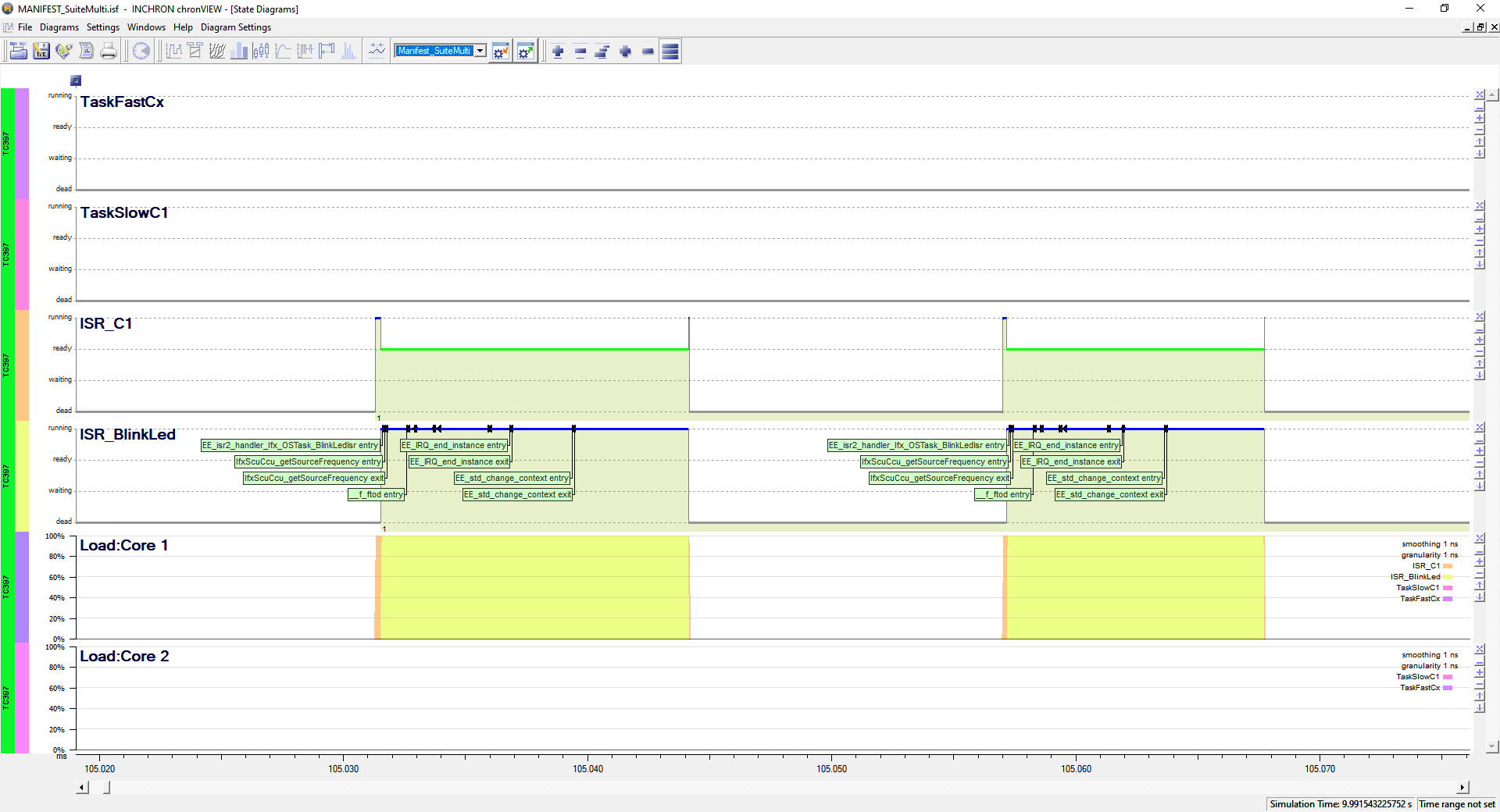
Dig deeply into your system’s real-time behaviour on Infineon AURIX devices. Look at the big picture, or at the finest details happening in a split second. The screenshot above shows the exact same scenario as the previous one, but zoomed into the very details of the interrupt service routines called at 105 ms on the time axis.
Optimized for User Experience and Performance
The chronSUITE is highly optimized for performance when it comes to navigating and zooming large trace files with file sizes in the GB range.
Automated Timing Analysis Based on MCDS Traces
[Click to enlarge]
Event Chain Visualization
A sequence of consecutive events, whereas each subsequent event is controlled, or supplied with data, by the preceding event, is called an event chain. Event chain information can be added, visualized, and integrated into the quantitative timing analysis using the chronSUITE.
Automated Timing Analysis Based on Timing Requirements
Maintaining a set of complete and consistent timing requirements is a precondition for a real-time system design that will work perfectly once completed. The chronSUITE systematically analyzes trace files to detect any violations (and near-to violations) of timing requirements.
Analysing Event Chain End-to-End Timing
From a systems point of view, end-to-end timing requirements from the start of the first event of an event chain to the end of the last event of that event chain, are particularly important. End-to-end timing requirements quite often define the user experience of a real-time system.
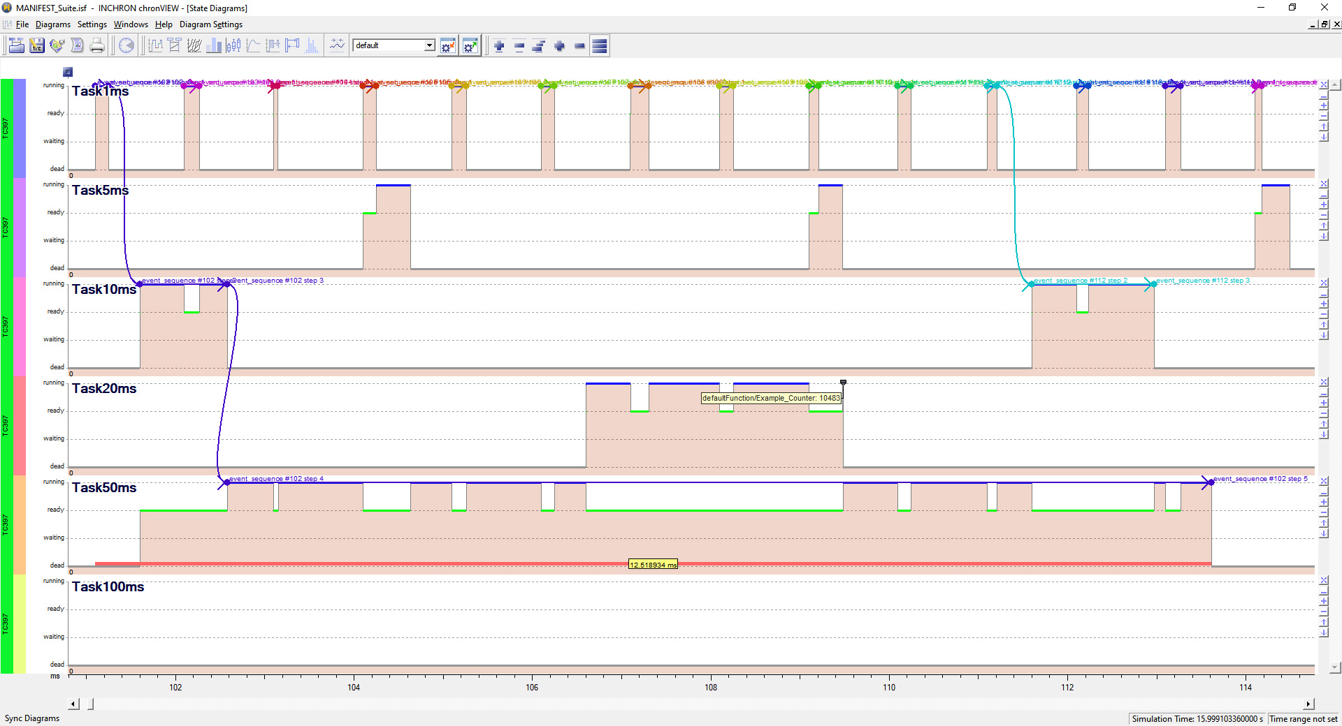
In the screenshot above, the event chains are shown as a sequence of bent arrows. The instance of the event chain that starts on the very left of the screenshot above violates its related end-to-end timing requirement and is therefore shown in red along the time axis of Task50ms. The measured end-to-end response time equals about 12.519 ms. In this particular case, the observed timing requirement violation is a direct consequence of the cumulated preemptions of Task50ms by higher priority tasks.
[Click to enlarge]
Specifying Timing Requirements and Analysing Timing Requirements Violations
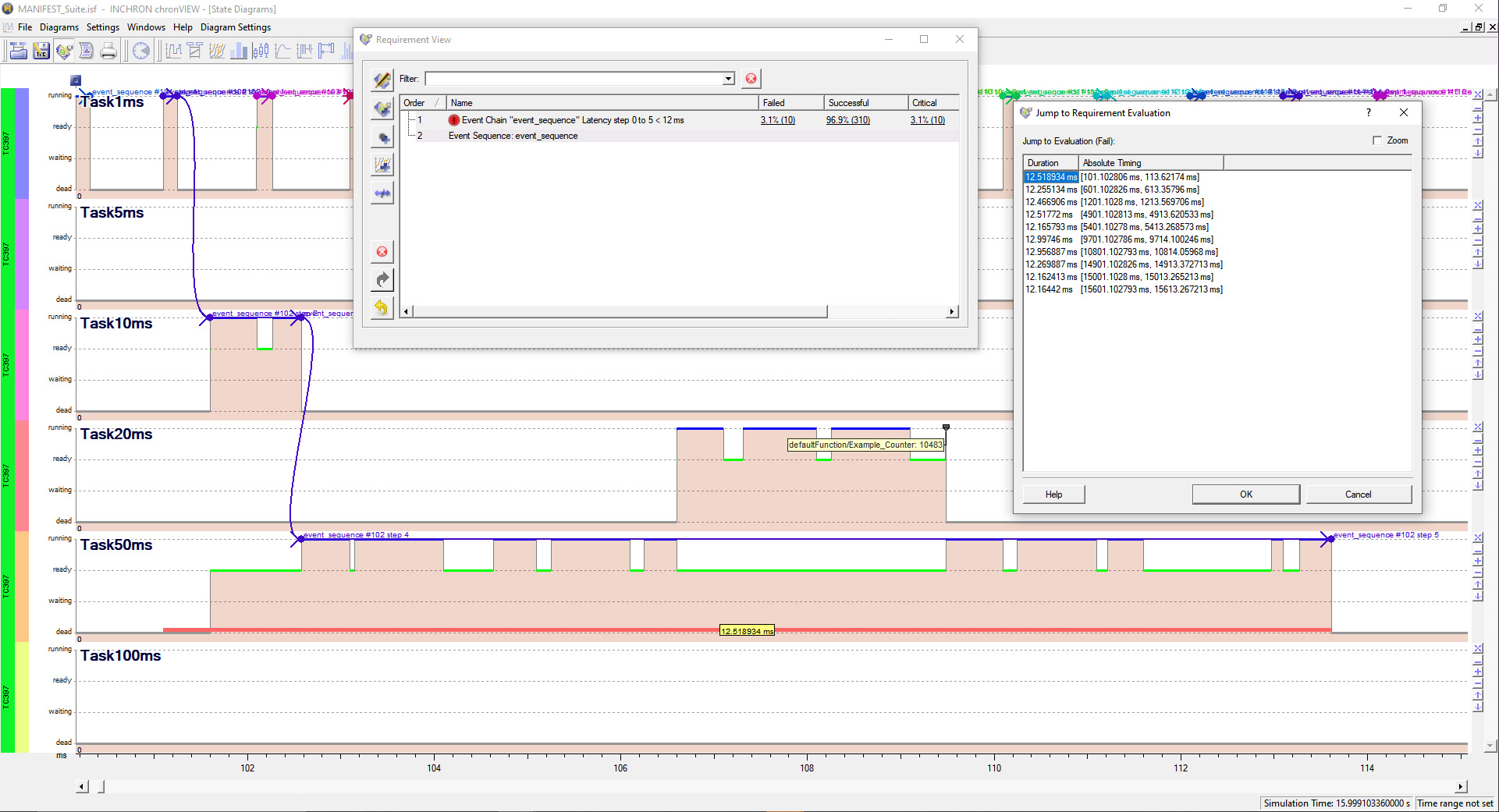
The screenshot above shows the “Requirement View” window. This is where timing requirements (and some other requirements not related to timing) can be entered or edited. In this example, just one requirement is shown: the event chain sequence latency across the event chain “event sequence” must be less than 12 ms. The exact definition of “event_sequence” is entered in row 2 of the Requirement View window. A red traffic light appears in row 1 indicating that there are one or more occurences in the trace file where the specified timing requirement is violated. Clicking the verdict count “Failed” of the requirement with the red traffic light opens the “Jump to Requirement Evaluation” window next to the Requirement View. The evaluation window lists all instances of requirement violations related to the respective requirement; clicking any of the entries opens up the related scenario in the process state diagram (as shown in the screenshot above) in order to analyse the root cause for the respective requirement violation.
Learn more
Checking Other Requirements
Beyond timing requirements, the chronSUITE supports a variety of functional requirement types related to limits set for call nesting or function recursion depth, occurences of RTOS failure or event chain breakoffs, load limits and others. See the chronSUITE User Manual for a complete list of supported requirement types.
[Click to enlarge]
How to Define Event Chain Latency Requirements
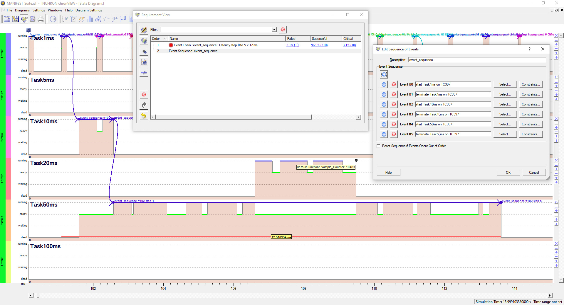
The definition of an event chain latency requirement comprises two steps: 1) The definition of the maximum of the tolerable latency, and 2) the exact definition of the event chain that maximum latency shall apply to. The “Edit Sequence of Events” window shown on the right hand side of the screenshot above is the place where all the steps of the event chain are defined.
Learn more
Identifying the Root Causes Behind Timing Requirement Violations
The most common root causes for timing requirement violations fall into a category that is characterized by simultaneous or overlapping software activities that compete for the limited resources available. In the example screenshot above, the preemptions of the repetitive tasks Task10ms, Task20ms and Task50ms are what mainly contributes to the requirement violations detected. Anticipating, analysing and fixing such requirement violations by developing proper timing models and using the simulation module (chronSIM) of the chronSUITE definitely help to avoid such issues right from the beginning of the development, even before any target hardware, or embedded software for that hardware, are available.
[Click to enlarge]
Displaying Values of Variables
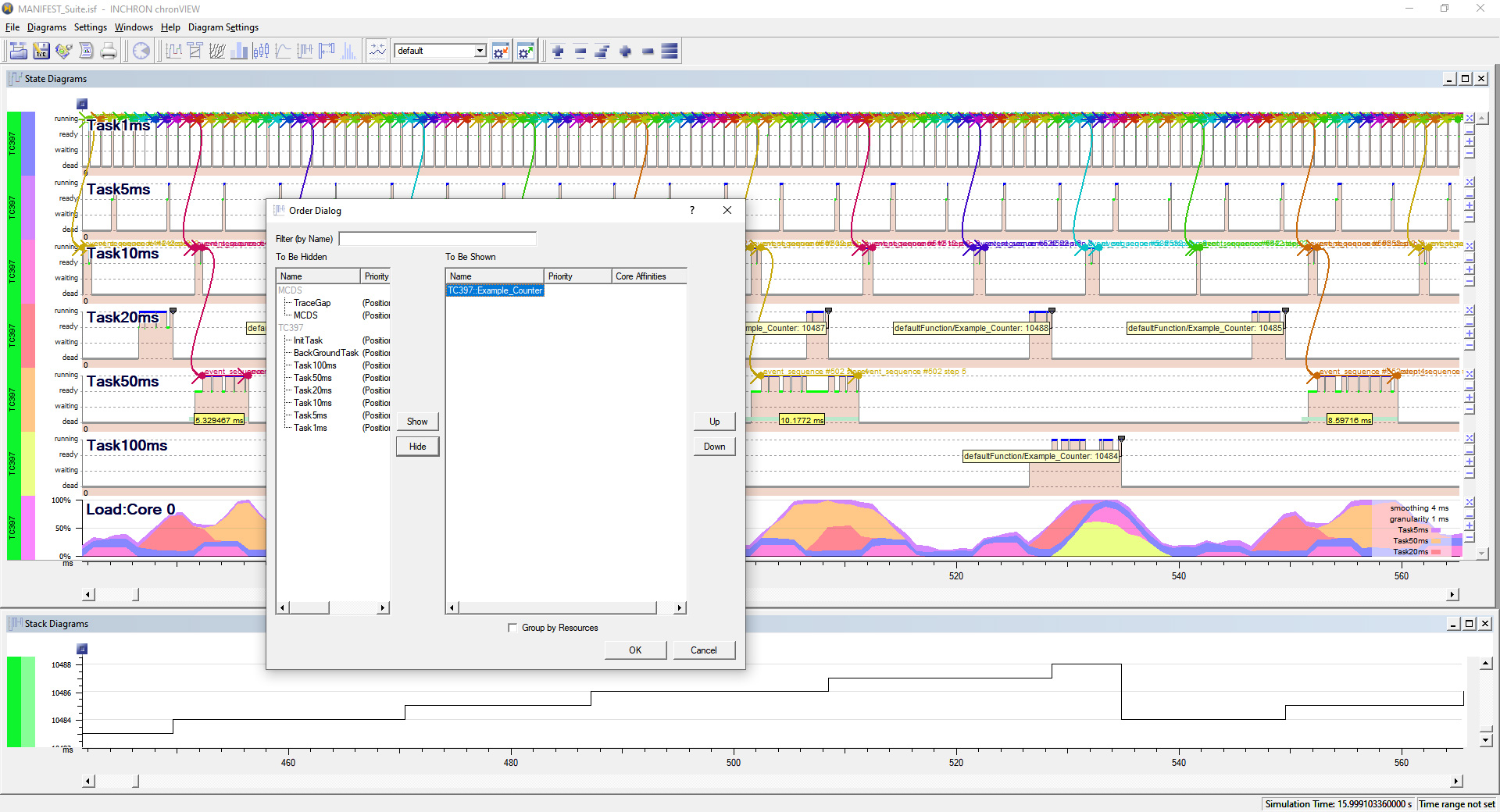
To facilitate the timing analysis of the system behavior, values of integer variables can also be displayed versus the time axis. Such variables may contain measurement results, control parameter values passed to the hardware, or any sorts of values providing additional insight into the behavior of the system’s algorithms.
The screenshot above shows a very simple instructional example:
By placing a stack diagram next to the state and load diagrams and syncing the time scales of all diagrams, the values of the Example_Counter are being displayed along with the task timing and processor core load information.
Using Third Party Tracing Solutions
The advantages of using the trace capabilities provided by Infineon’s MCDS are user friendliness, costs savings, and reduced form-factor requirements for non-intrusive tracing. AURIX emulation devices come with MCDS. In conjunction with the timing analysis capabilities of the INCHRON chronSUITE, this is a highly attractive solution for trace-based timing analysis.
It is worth to mention, however, that INCHRON does not leave users alone who need more advanced tracing solutions for specific purposes. The same kind of trace-based timing analysis with the chronSUITE as explained above also works right out-of-the box using trace logs generated by tracing solutions from our partners iSYSTEM, Lauterbach, PLS and Gliwa.
Learn more
Find more information in the application note “Comprehensive Real-Time Analysis on Infineon AURIX”
chronVIEW is the chronSUITE module that provides all the trace analysis features mentioned above
Infineon’s DAS (Direct Access Server) tool interface runs on a PC and provides access to the AURIX device
Real-Time Performance Analysis on Infineon AURIX

