Keeping digital mirror video feeds in sync
Bulky side-view mirrors are out, and camera-based vision systems are replacing them. They have lower drag, provide a wider field of view, and reduce blind spots. But how can you ensure that the camera feeds are always in sync with reality?
For system architects, project managers, testers, and integrators at OEMs and Tier 1s.

For More Information, Get in Touch
If you’re looking for support with ECU performance monitoring, requirements engineering, or evaluation and optimization of your design, use the form below to get in touch.
More than a futuristic mirror solution
Commonly seen on commercial vehicles and in high-end consumer vehicles, digital mirrors offer a range of benefits. Vehicle designers attain more aesthetic freedom and aerodynamics experts achieve less drag. Inside the vehicle, merged camera feeds offer previously impossible all-round views.
This improves safety and provides better visibility when maneuvering.
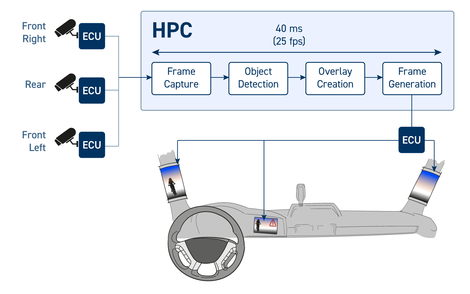
But new challenges arise for E/E system developers, especially with the move to new architectures. A core issue is timing – ensuring that the image displayed reflects, with minimal latency, the reality of the environment around the vehicle.
Furthermore, all video output, left and right, must remain in sync.
With cameras and displays sharing resources with other systems, and the latency of shared data busses, how do you overcome these design and development challenges?
Digital mirror latency challenges
- Synchronization of left/center/right display images
- End-to-end latency between road objects and appearance in digital mirror display
- Processing of video frames on shared ECU resource
- Sync of overlays with objects
- Distribution of software across multiple ECUs/Zone-Controllers/HPC
- Bandwidth of data busses (network load)
- Avoidance of dropped frames
- Failover time
Identifying digital mirror timing issues
Development teams become aware of synchronization issues during the integration phase of their project. Under specific operational conditions, when ECUs are fully loaded with tasks, overlays fail to synchronize with objects and frames are lost.
Sometimes there is a difference between the left, center, and right video feed. These issues are subtle, difficult to recreate during hardware testing, and challenging to debug.
Resolving digital mirror implementation challenges
At this stage it’s worth creating a model-based simulation. A combination of system measurements and estimation can be used to determine the end-to-end timing and latencies from camera to display. This is used to define all the event chains occurring through the system which the team uses to define the timing requirements.
Simulation allows potential bottlenecks to be discovered earlier, enabling changes to the system architecture to be made and supporting the selection of appropriate processors.
Later, when hardware is available, trace data from processors and network delays can be captured. With such data, it’s possible to compare the desired and actual functionality and determine the root cause of any issues that arise.
Input required to resolve issues
- Estimated delays from camera to digital mirror display
- System requirements
- System architecture
- Trace data from ECU/HPC processors
INCHRON approach
The INCHRON team will review the available requirements documentation and assess the end-to-end timing estimation.
Using our chronSUITE tools, the team will analyze available trace data and provide feedback on changes that will either lead to further insights or resolve the issues seen. The model developed can then be used for future designs to ensure timing is considered from project kick-off and avoid timing-related issues.
Recommended INCHRON services and tools
Development team’s benefits
- Simulation, analysis, and exploration before architecture decision
- Ongoing monitoring of end-to-end system latencies
- Reporting
- Issue-related stakeholder identification

Get in Touch
If you’re looking for support with ECU performance monitoring, requirements engineering, or evaluation and optimization of your design, use the form below to get in touch.

